
Expandable Barrier Installation Guide

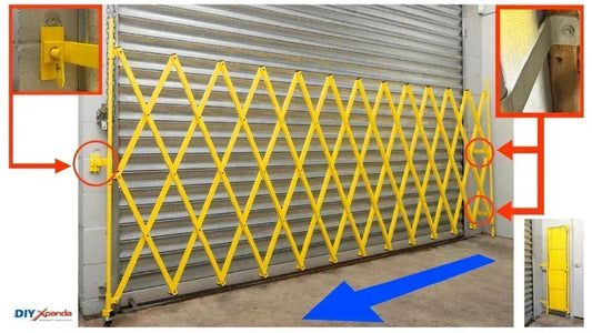
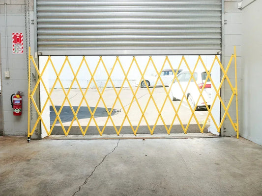
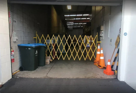
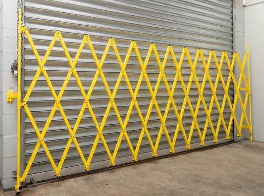
Yellow Expandable Barrier
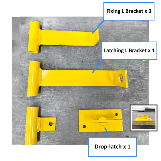
The yellow barrier uses:
- Three 130mm fixing L brackets
- One 200mm latching bracket
The fixing brackets are positioned along the fixed side of the barrier.
View Yellow Expandable Barrier Installation Guide
Expandable barriers are designed to help control pedestrian access and temporarily restrict entrances, workshops, roller doors and other areas. They are not designed to provide the same level of protection as a steel security gate.
Expandable Barrier Components
Your barrier includes:
- Expandable barrier panel made from aluminium tubing
- 1 × 200mm latching L bracket
- 3 × 130mm fixing L brackets
- 2 × barrier brackets
- 1 × Anti-Luce wall fastener, also known as a drop latch or trailer latch
- Swivel castor with foot lock
The 200mm latching L bracket may be supplied in a zinc-coated finish instead of powder-coated yellow, depending on stock availability.
Note: Screws and fixings are not included. An 8mm Dynabolt is recommended for fixing into concrete, while a suitable hex-head wood screw is recommended for fixing into a timber frame. Always confirm that the fixing type and length are appropriate for the mounting surface.


Step 1: Measure the Entrance
Before selecting or installing your expandable barrier, measure the area you want to cover.
Measure:
- The full width of the entrance
- The required barrier height
Measure the width from the intended fixing point on one side to the locking point on the opposite side.

Step 2: Check the Distance from the Door or Roller Door
Position the expandable barrier far enough away from the door or roller door so that both systems can operate without touching.
Before drilling:
- Open and close the door or roller door.
- Make sure the roller door can lower fully without resting on the barrier.
If the roller door comes down onto the barrier, it may damage the barrier or place unnecessary strain on the roller-door motor.
The barrier can often be installed behind the roller-door track, provided there is a suitable timber stud, concrete surface or other strong fixing point. The transcript also stresses checking for obstacles such as a nearby power box before deciding the final fixing position.

Step 3: Choose the Fixing Direction
The barrier may be installed using either a face-fix or sill-fix arrangement, depending on the opening and available mounting surface.
Face Fix
The brackets are fixed onto the front face of the wall, frame or supporting structure.
Face fixing may be suitable when:
- There is a strong flat surface beside the opening
- The barrier needs to sit in front of the opening
- There is not enough suitable space inside the entrance
Sill Fix
The brackets are fixed into the side or rear surface of the opening.
Sill fixing may be suitable when:
- There is a timber stud behind the frame
- There is a concrete side wall
- The barrier can sit further back from the entrance
- A cleaner and straighter installation line is available
Choose the fixing direction that provides the strongest practical fixing point while keeping the barrier clear of the door, roller-door track and other obstacles.

Step 4: Position the Fixing Brackets
The three 130mm fixing L brackets secure the fixed side of the expandable barrier to the mounting surface.
Position the brackets along the side of the barrier.
Important positioning requirements
- Leave a small gap between each fixing L bracket and the barrier bracket.
- Do not position the fixing bracket so high that it interferes with the barrier slides.
- The brackets should generally remain below the next rivet line.
- The barrier slides must be able to move downward when the barrier extends.
A small clearance between the fixing bracket and barrier bracket is important. If they press against each other, the barrier may not extend or retract smoothly.

Where an obstacle prevents the preferred position, the bracket can be moved slightly upward, but it should not be positioned above the recommended rivet area.
Step 5: Mark and Drill the Fixed Side
Once the position has been confirmed:
- Hold the barrier in its intended position.
- Check that it is straight and vertically aligned.
- Mark the fixing holes through the L brackets.
- Confirm that the marks align with solid timber, concrete or another suitable structural surface.
- Drill the required holes.
- Fix the brackets securely.
For concrete, use suitable 8mm Dynabolts where appropriate.
For timber framing, use suitable hex-head wood screws of the correct length and diameter.
Do not rely on thin wall lining, decorative trim or unsupported material as the main fixing point.

Step 6: Test the Barrier Alignment
After securing the fixed side, slowly extend the barrier across the entrance.
Check that:
- The barrier travels in a straight line
- The castor rolls smoothly
- The barrier does not twist
- The slides can move downward freely
- The opposite locking side reaches the intended position
- The barrier remains clear of the door or roller door
Do not permanently install the locking side until the barrier has been fully extended and its final position confirmed.

How to Extend and Retract the Barrier
Use the 200mm latching L bracket as the operating handle.
Do not allow the latching bracket to swing back into the barrier while it is retracting. This may cause it to catch and could bend the castor-side post. The transcript recommends using the bracket as the handle and folding it safely out of the way during operation.

Step 7: Install the Anti-Luce Wall Fastener
The Anti-Luce wall fastener is also commonly called a:
- Drop latch
- Trailer latch
- Anti-Luce fastener
Install it on the opposite side of the opening after the barrier has been fully extended and aligned.
Installation position
- Extend the barrier to the required width.
- Hold the latching L bracket against the opposite fixing surface.
- Position the Anti-Luce fastener between the barrier slides.
- Aim for a central position where practical.
- Leave enough clearance between the latch, bracket and moving slides.
- Mark and drill the fixing holes.
- Secure the fastener to a suitable structural surface.
The latching L bracket should fit over the Anti-Luce fastener and drop downward into the secured position.

Lock the Barrier
A padlock may be fitted through the lower section of the Anti-Luce fastener.
Use a padlock with a shackle no greater than 8mm in diameter.
For the strongest locking position:
- Drop the latching bracket completely over the Anti-Luce fastener.
- Insert the padlock through the lower locking hole.
- Confirm that the bracket cannot be lifted upward.
- Lock the padlock and test the barrier.
Installing the padlock too high may allow the bracket to lift slightly and create unnecessary movement. The lower locking position is recommended because it prevents the latch from being raised without removing the padlock.

Step 8: Adjust the Swivel Castor
The swivel castor supports the moving side of the barrier.
Check that:
- The castor remains in contact with the floor
- It rolls smoothly across the full opening
- It does not carry excessive weight
- The barrier remains upright
- The foot lock operates correctly
Use the foot lock to help hold the barrier in position when required.
Uneven floors may affect how smoothly the barrier moves. Test the full travel distance before completing the installation.

Expandable Barriers vs Security Gates
A Yellow Expandable Barrier is primarily an access-control and pedestrian-management barrier.
It can help:
- Restrict entry into a work area
- Control pedestrian movement
- Close off a roller-door entrance
- Create a visible boundary
- Temporarily restrict access
- Separate customers from operational areas
However, it is not designed to provide the same protection as a steel security gate.
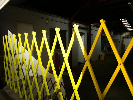
The open diamond pattern is relatively large, and the aluminium barrier remains flexible. A person may still be able to reach through, move the barrier or access items positioned too close behind it.
For this reason:
- Do not install it directly in front of a window that requires burglary protection.
- Keep valuable items away from the barrier.
- Do not treat it as a substitute for a security grille.
- Do not rely on it as the only security measure for a high-risk entrance.
For stronger protection, consider a steel security gate such as Saftidor, which has narrower diamond openings and a more rigid steel construction. The transcript clearly distinguishes the expandable barrier as an access-control product rather than a full security gate.

Final Installation Check
Before using the barrier, confirm that:
- The opening was measured correctly
- All brackets are fixed into suitable structural material
- The barrier is straight
- The barrier does not interfere with the door or roller door
- All moving slides have sufficient clearance
- The castor moves smoothly
- The latching bracket operates correctly
- The Anti-Luce fastener is securely installed
- The padlock fits through the lower locking point
- The barrier extends and retracts without catching
Stop using the barrier if any bracket, rivet, castor or fixing becomes loose or damaged.
Need Installation Help?
Send DIY Xpanda:
- A clear photo of the entrance
- The opening width
- The required barrier height
- Photos of both fixing surfaces
- Details of whether the fixing surfaces are timber, concrete or another material
This will help us confirm the most suitable barrier size, fixing direction and installation position.
Check out the video here for a more detailed installation guide.

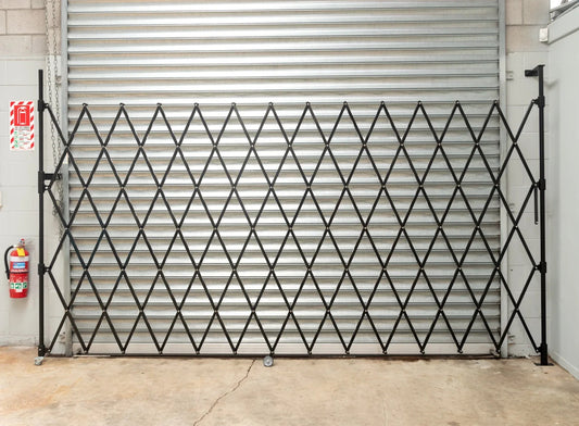
Black Expandable Barrier
The black barrier uses:
- One 130mm floor fixing bracket
- One 200mm top fixing bracket
- One 200mm locking bracket
The fixed side is secured at the top and floor rather than with individual side brackets.
View Black Expandable Barrier Installation Guide
How to Install a Black Expandable Barrier
Expandable barriers are designed to help control pedestrian access and temporarily restrict entrances, workshops, roller doors and other areas. They are not designed to provide the same level of protection as a steel security gate.
Black Expandable Barrier Components
- Expandable barrier panel made from aluminium tubing
- 1 × 200mm top fixing bracket
- 1 × 130mm floor fixing bracket
- 1 × 200mm locking bracket
- 1 × Anti-Luce wall fastener, also known as a drop latch or trailer latch
- Swivel castor with foot lock
- Note: Screws and fixings are not included.
Step 1: Measure the Entrance
Before selecting or installing your expandable barrier, measure the area you want to cover. Measure:
- The full width of the entrance
- The required barrier height
- The available floor and upper fixing surfaces
Measure the width from the intended fixed side of the barrier to the locking point on the opposite side. Also confirm that there is enough space for the barrier to retract when it is not in use.

Step 2: Check the Distance from the Door or Roller Door
Position the expandable barrier far enough away from the door or roller door so that both systems can operate without touching. Before drilling:
- Open and close the door or roller door.
- Check that the barrier will not catch on handles, tracks, hinges or other fittings.
- Make sure the roller door can lower fully without resting on the barrier.
- Check for obstacles such as power boxes, pipes or wall fittings.
- Confirm that the barrier will not block the clear opening when retracted.
If a roller door comes down onto the barrier, it may damage the barrier or place unnecessary strain on the roller-door motor. The barrier can often be installed behind a roller-door track, provided there is a suitable concrete, timber or other structurally sound fixing surface.
Step 3: Choose the Fixing Direction
The black expandable barrier can be installed in different positions depending on the entrance, available fixing surfaces and required distance from the door.
Face Fix
The top fixing bracket is secured onto the front face of the wall, frame or supporting structure. Face fixing may be suitable when:
- There is a strong, flat surface above or beside the opening
- The barrier needs to sit in front of the entrance
- There is not enough suitable space inside the opening
- The barrier must remain clear of a roller-door track
Sill Fix
The top fixing bracket is secured into an internal, side-facing or rear surface of the opening. Sill fixing may be suitable when:
- There is a timber stud behind the frame
- There is a concrete wall or lintel
- The barrier can sit further back from the entrance
- A straighter or more secure fixing position is available
Choose the position that provides the strongest practical fixing point while keeping the barrier clear of the door, roller-door track and other obstacles.
Step 4: Position the Top and Floor Fixing Brackets
Unlike the yellow expandable barrier, which uses several individual side brackets, the black expandable barrier is secured using a top fixing bracket and a floor fixing bracket.
The fixing system includes:
- A 200mm top fixing bracket
- A 130mm floor fixing bracket
- Mounting plates with fixing holes
The top and floor brackets secure the fixed side of the barrier and help keep it upright during operation.

Positioning requirements
- Position the barrier vertically.
- Align the top and floor brackets with each other.
- Make sure the floor bracket sits on a solid and level surface.
- Confirm that the top bracket connects to structural timber, concrete or another suitable fixing point.
- Keep the brackets clear of the barrier’s moving slides.
- Make sure the barrier can extend and retract without rubbing against the brackets.
- Check that the swivel castor remains in contact with the floor.
The black barrier uses a bottom and top mounting arrangement rather than the individual side brackets supplied with the yellow barrier.
Step 5: Mark and Drill the Fixed Side
Once the barrier position has been confirmed:
- Hold the barrier upright in its intended location.
- Check that it is straight and vertically aligned.
- Position the floor fixing bracket at the base of the fixed side.
- Position the top fixing bracket directly above it.
- Mark the fixing holes through both brackets.
- Confirm that the marks align with suitable structural material.
- Drill the required holes.
- Secure the floor and top fixing brackets.
- Check the barrier alignment again before fully tightening all fixings.
For concrete, use suitable 8mm Dynabolts where appropriate.
For timber framing, use suitable hex-head wood screws of the correct diameter and length.

Step 6: Test the Barrier Alignment
After securing the fixed side, slowly extend the barrier across the entrance.
Use the 200mm locking bracket as the operating handle. Allowing the locking bracket to catch inside the barrier may damage or bend the castor-side post.

Check that:
- The barrier travels in a straight line
- The swivel castor rolls smoothly
- The barrier does not twist or lean
- The slides move freely
- The locking side reaches the intended position
- The barrier remains clear of the door or roller door
- The top and floor brackets remain secure

Step 7: Install the Anti-Luce Wall Fastener
The Anti-Luce wall fastener is also commonly called a:
- Drop latch
- Trailer latch
- Anti-Luce fastener
Install it on the opposite side of the opening after the barrier has been fully extended and aligned.
Installation Position
- Extend the barrier to the required width.
- Hold the locking bracket against the opposite fixing surface.
- Position the Anti-Luce fastener between the barrier slides.
- Aim for a central position where practical.
- Leave sufficient clearance between the fastener, bracket and moving slides.
- Confirm that the locking bracket can drop completely over the fastener.
- Mark and drill the fixing holes.
- Secure the fastener to a suitable structural surface.
- Extend and retract the barrier again to test the alignment.
The locking bracket should fit over the Anti-Luce fastener and drop downward into the secured position.


Lock the Barrier
A padlock may be fitted through the lower section of the Anti-Luce fastener.
Use a padlock with a shackle no greater than 8mm in diameter.
For the strongest locking position:
- Drop the locking bracket completely over the Anti-Luce fastener.
- Insert the padlock through the lower locking hole.
- Confirm that the bracket cannot be lifted upward.
- Lock the padlock.
- Test that the barrier remains secured.
Installing the padlock through a higher position may allow the bracket to lift slightly and create a gap. The lower locking position is recommended because it prevents the bracket from being raised without first removing the padlock.
Step 8: Adjust the Swivel Castor
The swivel castor supports the moving side of the barrier.
Check that:
- The castor remains in contact with the floor
- It rolls smoothly across the full opening
- It does not carry excessive weight
- The barrier remains upright
- The foot lock operates correctly
- The barrier does not pull against the top or floor mounting bracket
Use the foot lock to help hold the barrier in position when required.
Uneven floors may affect how smoothly the barrier moves. Test the full travel distance before completing the installation.

Expandable Barriers vs Security Gates
A Black Expandable Barrier is primarily an access-control and pedestrian-management barrier.
It can help:
- Restrict entry into a work area
- Control pedestrian movement
- Close off a roller-door entrance
- Create a visible boundary
- Temporarily restrict access
- Separate customers from operational areas
However, it is not designed to provide the same protection as a steel security gate.
The open diamond pattern is relatively large, and the aluminium barrier remains flexible. A person may still be able to reach through, move the barrier or access items positioned too close behind it.
For this reason:
- Do not install it directly in front of a window that requires burglary protection.
- Keep valuable items away from the barrier.
- Do not treat it as a substitute for a security grille.
- Do not rely on it as the only security measure for a high-risk entrance.
- Do not use it as a child-safety or fall-prevention barrier.
For stronger protection, consider a steel security gate such as Saftidor. Its steel construction and narrower diamond openings provide a stronger physical barrier than an aluminium expandable access-control barrier.

Final Installation Check
Before using the barrier, confirm that:
- The opening was measured correctly
- The top and floor brackets are securely installed
- All fixings connect to suitable structural material
- The barrier is straight and vertically aligned
- The barrier does not interfere with the door or roller door
- The moving slides have sufficient clearance
- The swivel castor moves smoothly
- The locking bracket operates correctly
- The Anti-Luce fastener is securely installed
- The padlock fits through the lower locking point
- The barrier extends and retracts without catching
- The barrier remains stable in both its open and closed positions
Stop using the barrier if any bracket, rivet, castor or fixing becomes loose or damaged.

Need Installation Help?
Send DIY Xpanda:
- A clear photo of the entrance
- The opening width
- The required barrier height
- Photos of the floor and upper fixing surfaces
- Details of whether the fixing surfaces are timber, concrete or another material
- Information about any nearby doors, roller-door tracks or obstacles
This will help us confirm the most suitable barrier size, fixing direction and installation position.
Check out the installation video for a more detailed guide.
Due to the size of the barrier shown in the installation video, an additional fixing bracket was installed to reinforce the barrier and improve its durability.
Expandable Barriers for Homes
-
Expandable Barrier Black 4m Wide 1.3m High (A)
Regular price $852.00 NZDRegular price$852.00 NZDSale price $852.00 NZD -
Expandable Barrier Black 4m Wide 1.9m High (B)
Regular price $1,385.50 NZDRegular price$1,385.50 NZDSale price $1,385.50 NZD -
Expandable Barrier Yellow 3m Wide 1.0m High (A)
Regular price $798.00 NZDRegular price$798.00 NZDSale price $798.00 NZD -
Expandable Barrier Yellow 4m Wide 1.0m High (B)
Regular price $1,092.50 NZDRegular price$1,092.50 NZDSale price $1,092.50 NZD -
Expandable Barrier Yellow 4m Wide 2.0m High (C)
Regular price $1,650.00 NZDRegular price$1,650.00 NZDSale price $1,650.00 NZD -
Expandable Barrier Yellow 5m Wide 1.0m High (D)
Regular price $1,366.00 NZDRegular price$1,366.00 NZDSale price $1,366.00 NZD -
Expandable Barrier Yellow 6m Wide 1.5m High (E)
Regular price $1,900.00 NZDRegular price$1,900.00 NZDSale price $1,900.00 NZD -
Expandable Barrier Yellow 8m Wide 1.5m High (F)
Regular price $2,622.00 NZDRegular price$2,622.00 NZDSale price $2,622.00 NZD -
Expandable Barrier Yellow 8m Wide 2.0m High (G)
Regular price $3,059.00 NZDRegular price$3,059.00 NZDSale price $3,059.00 NZD -
Expandable Pedestrian Barrier Rental 6m Wide 2m High
Regular price From $700.00 NZDRegular price$700.00 NZDSale price From $700.00 NZD